BitBug analog bitcrusher
So, the bitcrusher. You know, that classic digital effect used by everything from daft punk to artists that have had original ideas in their career? Those are pretty cool right? The whole adjusting intrinsic aspects of digital audio to give sounds a completely new character. What if we were to take this pretty simple effect and replicate it in the analog domain with great difficulty? That seems like a meaningful and reasonable idea and use of time, right? Right?
Concept
How do we approach this task? Well, a bitcrusher does two things: It reduces the resolution of digital samples, and reduces the sample rate of the signal. Let’s focus on the first part for now. The second part is really just making a sample-and-hold circuit of variable speed.
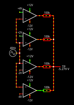
So, we want to take an analog signal in, quantise it somehow, and then output something reflecting that quantisation. Well, what if we were to compare the signal with a set of voltages off a resistor ladder, we would indeed get a set of digital outputs, each pulling high in sequence as the signal level increases. Neat. Now how to turn that back into an analog signal? Maybe some half-complex ladder dac setup? That sounds a bit difficult. Rather, if the comparators we had were of a push-pull variety and mirrored across the zero crossing in equidistant steps, all could just connected together through current limiting resistors, and the resulting signal would span the output ranges of the comparators. At 0V, half of the comparators would push and the other half would pull, resulting in a 0V output. As the signal level changes the proportion of pushing and pulling op-amps would similarly change, producing a stepped output.
Now comparators for this uncommon task are pretty impossible to come by, so why don’t we just use op-amps for the task? At this point, if you are an electronic engineer, you may be screaming at your screen. Yes, you are right. We’ll get to it. So, something along these lines:
In practice this circuit is equivalent to the first half of a flash ADC just directly feeding the output, each step of the ladder pushing and pulling to ultimately replicate the input. So just arrange all this into an actual circuit, and we’ve got half of an analog bitcrusher. Let’s give it a try.
Implementation
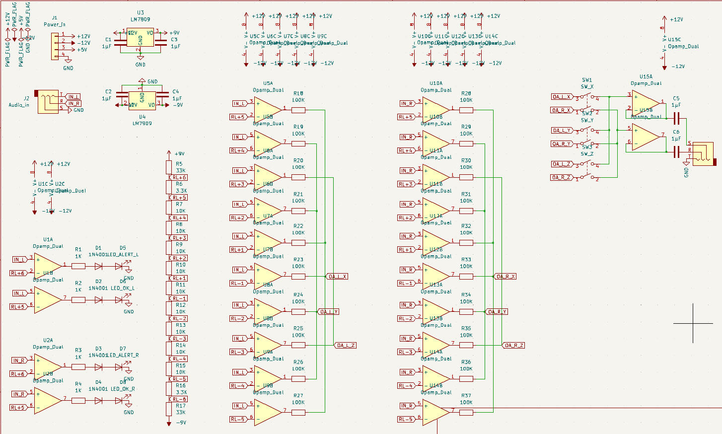
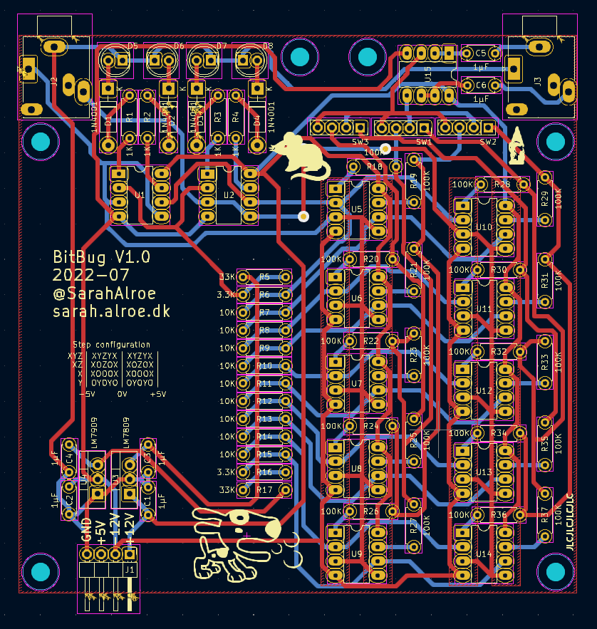
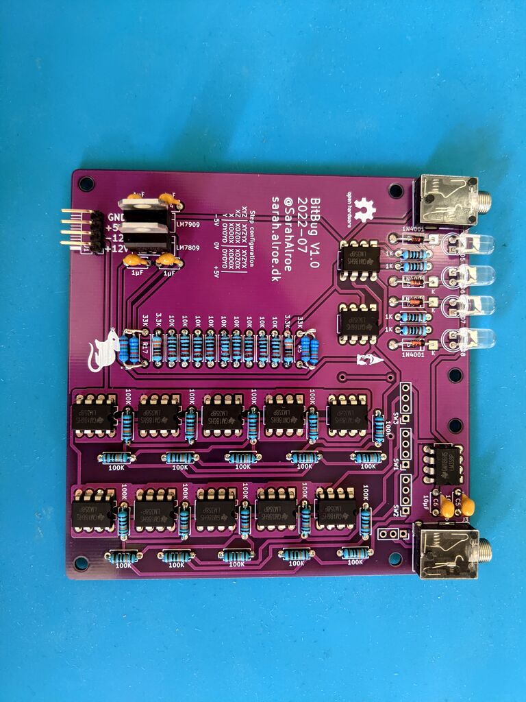
The circuit was drawn up in KiCad. In addition to the basic circuit, I added a regulated +-9V supply for the resistor ladder, and a couple of level indicators, as I correctly assumed utilising the entire range of the circuit would be essential for producing any meaningful results. I further added a couple of switches to enable or disable pairs of comparators, and a voltage follower to output a low-impedance signal. The PCB was sent off for production, and assembled as soon as I got it in the door.
Let’s give it a try.
Results?
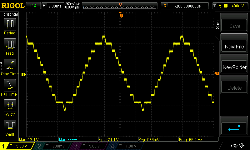
Nice! Feeding in a sine wave, it produces a nice stepped output… But wait a minute. Why does my scope say vpp=24V? That’s supposed to be 10V. Right, the op-amps pull to their high and low input voltages (minus a bit), which in this case is the +/-12V rail. Okay so turn the output voltage follower into an attenuation circuit and we’re good, right?
Well look at those slopes between each quantisation step. Those aren’t particularly steep. And that’s only at 100 hz. My lack of an electronics education bites me in the butt again. As far as I can tell, what is happening here is the result of the very slow slew rate characteristic of the LM358 op-amps that I used. Op-amps take a little while to change their output voltage. This is not usually a problem when dealing with lower voltages and just scaling the input. What is happening here however, is an op-amp which has to, as close to instantly as possible, jump straight from -12V to +12V, right as the input signal crosses a particular level. So even if these op-amps are just capable of following an audio signal within this voltage range, the fact that they have to traverse this entire range for just a fraction of the input waveform means they must be much faster to keep up for this job.
Among additional potential problems is that the outputs of op-amps saturate when used as comparators, which apparently takes additional time to recover from, as well as internal compensation, which I don’t quite understand, but which may play a part here. In short, op-amps are not the right tools for this job. Oh well. Let’s order some chips with a faster slew rate, and see what we can actually get out of it as it is.
Results
So the thing surprisingly works. It is quite ringy and noisy, but that certainly is the sound of a bitcrusher, albeit a weird and dirty sounding one.
Future work
Right, so that was an okay first attempt. What’s next on the list?
- Lay down the 9v regulators. Currently they’re the tallest things on this entire board.
- Turn the voltage follower into a proper attenuator.
- Build a circuit with some higher slew-rate op-amps, and see what that changes.
- Maybe regulate the op-amp supplies to ensure a consistent waveform?
- Build the sample-and-hold part of the bitcrusher.
Lots to do. I will probably make a post about it when I get further with the project.
As allways, the module design files can be found at github.