Landline Microphone adapter
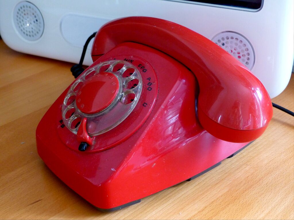
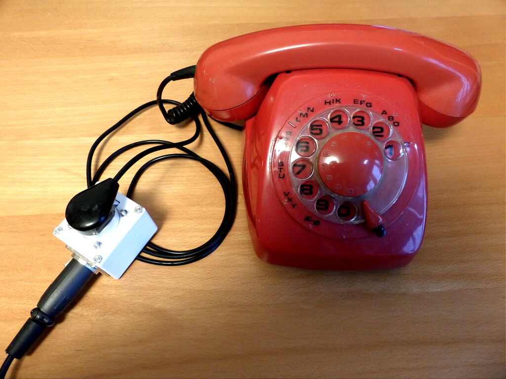
So I bought an old landline phone.
 Partially because I wanted to play around with PBX systems, partially because I wanted to try building a carbon microphone for studio use.
This is about the second idea.
Partially because I wanted to play around with PBX systems, partially because I wanted to try building a carbon microphone for studio use.
This is about the second idea.
Premise
First challenge: Carbon microphones (and because of that, landline phones) produce signals through variations in biased current.
Carbon microphones are an incredibly simple form of microphone, simply consisting of granules of carbon packed between two electrodes, one of them a flexible diaphragm. As the diaphragm is flexed by changes in air pressure, it compresses and decompresses the granules, increasing and decreasing the resistance across them. By providing a constant voltage across the microphone, a change in current is produced in accordance with changes in pressure, creating an audio current signal.
As the microphone is just a variable resistor a base dc current must constantly flow, making it impossible to just plug these microphones directly into a normal audio interface.
Methods for transforming this biased current signal into an unbiased voltage signal of course exist, and are pretty simple.
One circuit for doing this is provided in the manual for the Shure 104C microphone:
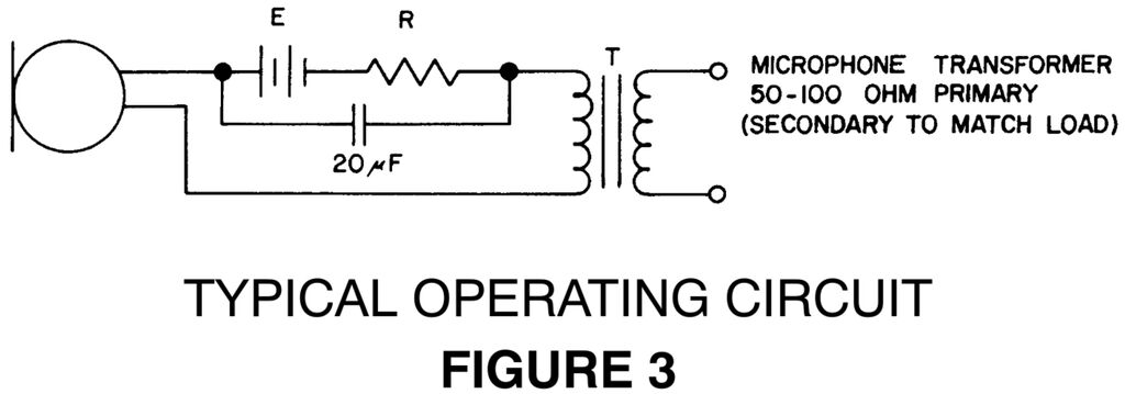 By passing the current through a transformer, the variation in current can be siphoned off while leaving the dc current alone to do its thing.
Second challenge: How does that relate to one of these?
 As I would like to use this phone for other things in the future, whatever done to it should be non-destructive.
Why not just create a box that the phone can plug directly into?
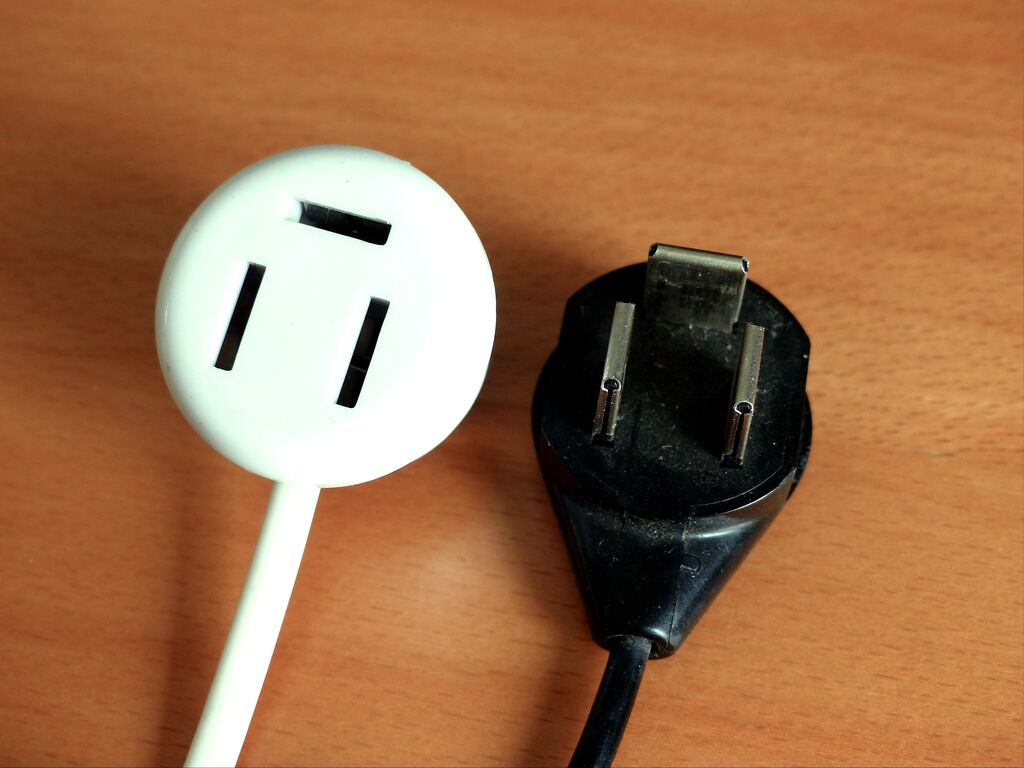
For any international readers, the above connector has been the standard landline phone connector in Denmark.
Apparently it has exclusively been used here. This made finding any information on it difficult.
After scouring the internet, here’s a summary of what you need to know:
As I would like to use this phone for other things in the future, whatever done to it should be non-destructive.
Why not just create a box that the phone can plug directly into?
For any international readers, the above connector has been the standard landline phone connector in Denmark.
Apparently it has exclusively been used here. This made finding any information on it difficult.
After scouring the internet, here’s a summary of what you need to know:
- Only the two vertical pins of the connector are used. The third remains unconnected.
- These phones work just like any other POTS phone, which means:
- The phone expects a nominal voltage of 48V across the two pins, but will work at much lower voltages.
- The phone will behave as though the transducer and microphone of the phone is just connected in series from T to R, and for this one it may well be.
- The polarity of the socket (with the horizontal pin at the top) is right positive (0V), left negative (-48V). By what resources I could find, this does not seem to matter much, though I have not confirmed this.
So, build a circuit that provides a voltage across the phone connector with a transformer winding in series, and pick up the signal on the other side of the transformer. No big deal.
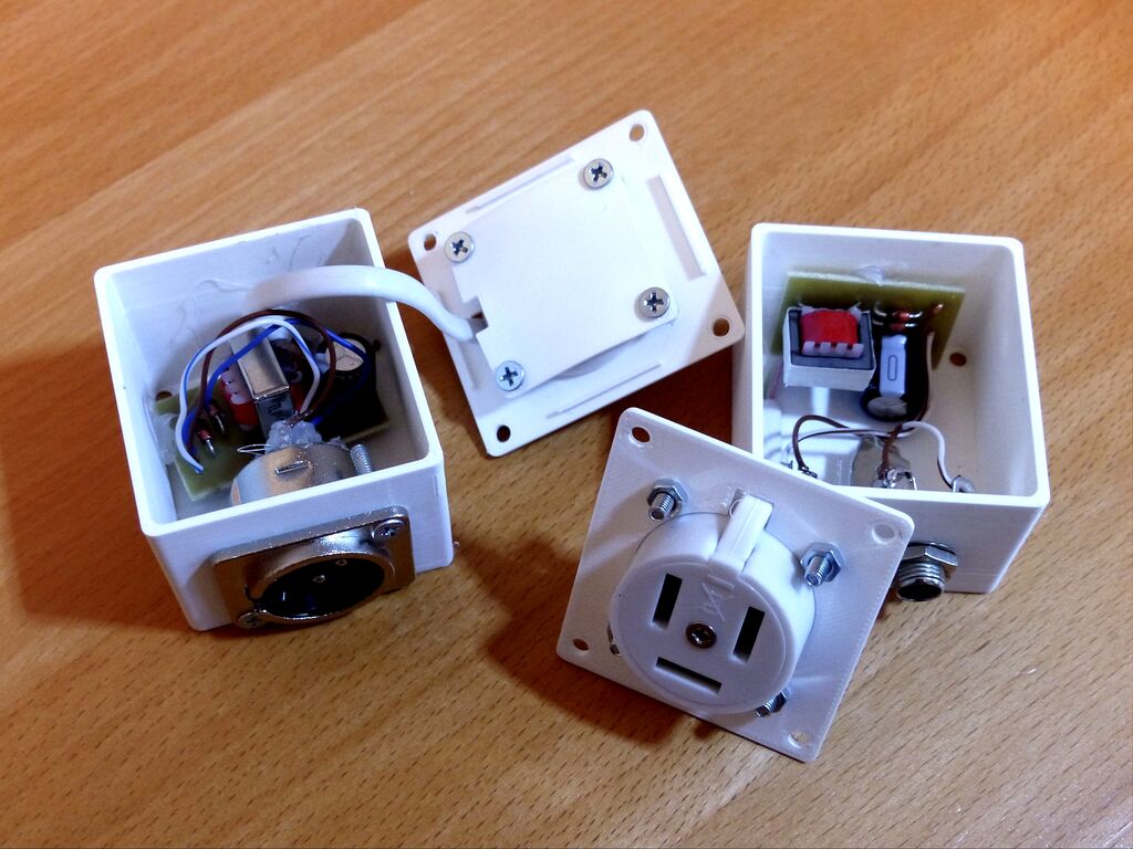
Development of a landline -> microphone adapter
So far, I have produced two variations of the circuit: One using an external power supply, and one using phantom power.
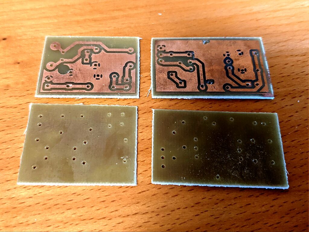
The circuits were designed in KiCad, and layouted in such a way they could easily be etched on a single sided board.
The externally powered circuit is very simple. Its only uncommon part is a 600:600ohm isolation transformer (here an EI14). It works exactly as the Shure circuit, with the addition of a zener diode based clamp at the output, to avoid voltage spikes from the shorts caused by the dialing mechanism.

 The phantom powered circuit works much the same, except that it uses a slightly more exotic isolation transformer with a center tap (here an 42TL016-RC). This allows drawing phantom power without affecting the balanced output signal. (On a sidenote there is a pretty good older EEVBlog video on phantom power worth watching to get an understanding of how it can be used.)

 As the resistance of the phone is itself quite high and designed for 48V nominal, the series resistor of the circuit does not need to be of any significant value. A value of 100ohm was selected as to somewhat limit the current in a short circuit situation without attenuating the signal too much. This value is just a best guess and not based on anything clever.
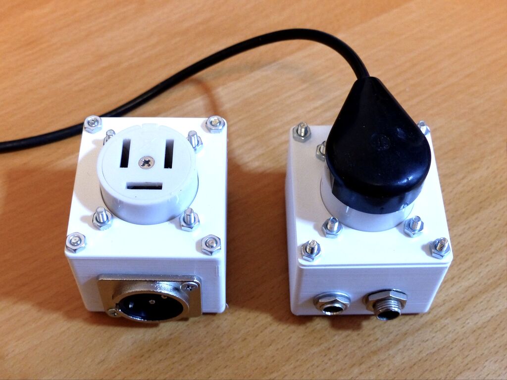
The circuits were then etched and soldered, and assembled into a 3d printed enclosure.
Results
 So yup. It works. At least sufficiently to produce recognisable audio.
This recording is made with the externally powered adapter, running on a battery.
This recording is made with the phantom powered adapter. It has a slight 50hz hum, but otherwise sounds great. The hum should easily be avoidable with a better audio interface, or better power supply for the interface. Just touching the case of the interface lowers the noise significantly.
I might try producing a response curve for the microphone later. Will be added here if I do.
Important notes:
- The circuit is quite sensitive to noisy power supplies. My solutions for this has been to either properly ground the supply, or use batteries.
- The dialing mechanism of old phones work by repeatedly shorting the line. This may cause some serious voltage spikes. Make sure to match the zener clamp to something lower than what might break your audio interface.
Future work includes making a eurorack compatible adapter, and potentially experimenting with non-transformer based circuits, as to avoid uncommon, heavy, and expensive components. Sources for the KiCad and 3D files, and a BOM can be found on github.com/SarahAlroe/TelephoneAdapter.